|
|
|
| |
|
| |
|
| |
|
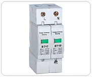
| BY40-40/2 |
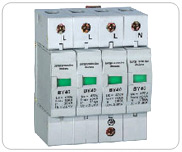
BY40-40/4 |
| |
1. Usage and application scope
|
| |
BY40 type surge protective device (short name "SPD") is suitable for AC 50/60 Hz,380V and the following electric power systems,such as TT, IT, TN-S, TN-C, TN-C-S. It protects the electric network shocked by the thunder or over voltage .
Working condition:
|
| |
2. Working condition: |
| |
1.Height: not more than 2000m
2. Operating temperature : normal -5~+40˚C Enlarge range: -40~+70˚C
3. Relative humidity: on condition that room temperature 30%~90%
4. Installed at no notability shocked and virated place
5. Don't be contained in explosion medium,the medium such as air and dust (including conduction dust ) shouldn't come to the degree that can corrode metal or damage insulation. |
| |
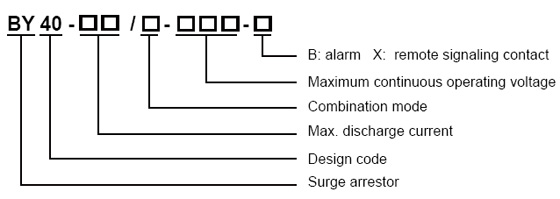
3. Model and meaning |
| |
|
| |
4. Tripping device |
| |
There is tripping device designed on the modular of the protector. When the protector is over heat or shocked, the tripping device can automatically separate it from the electric net, at the same time showing the indication signal. It¡¯s green when the protector is normal, red when tripping. |
| |
5. Alarm |
| |
The power of the alarm is supplied by AC220V. In normal condition it is green and the opening contact is closed but the closing contact is open. It is with the function of alarming and showing: the alarm will sound and the green indicator lamp will change to red when the mould of the protective device is out of working. And the alarm will not stop until the operator pushes the stop press (but the red lamp is still showing). If the trouble can not be dealt within 24 hours, the alarm will sound again. |
|
6. Remote signaling contact |
| |
The products can be produced available with the accessory of remote signaling contact. If one or more of modular of the protector is in malfuction, the contact will be closed, and sending the malfunction signal. |
| |
7. Principal parameters |
| |
Maximum continuous operating voltage : Uc 140 275 320 385 420 550 V~
Test grade:II
Voltage protect levelUp≤ 0.8 1.2 1.5 1.8 2.0 2.5kV
Maximum discharge current : (8/20μS) Imax 10 40 60 80kV
Nominal discharge currrent: (8/20μS) In 5 15 20 30 40kA |
| |
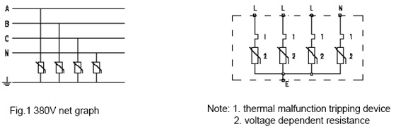
8. Main Structure and Operating Principle |
| |
In three-phase four- line system , three phase lines and one zero line are connected protective device to the earth cable . (figure 1 ) . In normal situation , the protective device is high resistance , when the over voltage brings for electric network shocked by thunder or other reasons , the protective device will rapidly transmit in ns , then lead the voltage into earth and protect the electric equipment . As the surge voltage through the protective device and after disappear it will recover to high resistance and not influence the normal operating. Pls refer to Fig.2 for the electric principal for the protector. |
| |
|
| |
9. Installation |
| |
1. It adopts 35 mm DIN rail
2. It is linked by 2.5 -- 35 mm² copper wire , and there are 2 wiring methods:
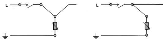
a) From power switch to protective device , then from protective device again to the load end . This way suits to the distribution case which load current is under 100 A . The wire section should be selected by the load current . ( refer to the figure )
b) From the power switch to protective device , also from the power switch to load end . This way suits to the distribution case which load current is over 100 A . The wire section should not be selected by the load current , but it can't be longer than 500 mm. (refer to the figure) |
| |
|
| |
3. The earth cable should choose the double color wire which is over 4 mm² but not longer than 500 mm .
4. In order to guarantee electrical network's normal operating after protective device losing efficiency , the protective device which linked to the phase line must be connected a fuse like Fig.2 .Pls refer to the appearance and installation dimension about the device like the figure. |
| |
10. Technical Parameters : |
| |
|
BY40-10/ -140 |
BY40-10/ -275 |
BY40-10/ -320 |
BY40-10/ -385 |
BY40-10/ -420 |
BY40-40/ -140 |
BY40-40/ -275 |
Maximum continuous operating voltage Uc |
140 |
275 |
320 |
385 |
420 |
140 |
275 |
Voltage protection level Up < |
2 |
2 |
5 |
5 |
15 |
15 |
20 |
Nominal discharge current In(8/20 µ s) kA |
0.8 |
1.5 |
1.5 |
2.0 |
2.0 |
0.8 |
1.2 |
Maximum discharge current Imax (8/20 µ s) kA |
10 |
10 |
10 |
10 |
10 |
40 |
40 |
Max. fuse intensity |
1632 |
Response time ns |
< 25 |
Width mm |
18 |
Color |
gray |
Protection level |
IP20 |
Shell material |
Reinforced fire-retardant nylon PBT |
Connect ways |
L ,N |
2.5 --- 35 mm2 |
Earthing |
4.0 --- 35mm2 |
Signal line |
1.5 mm2 |
|
|
| |
| |
| |
|